The OSI Model

The Open Systems Interconnect (OSI) Model dates back to 1984, and was the first introduction of a cross-vendor standard method of network communications.
Before that, every vendor had their own ways of shifting data, and troubleshooting was complicated. With the introduction of layers, errors could be confined to certain aspects, such as a physical issue or a routing issue.
The core concept of the model is encapsulation, the process where data is added or removed depending on the direction of travel.
In this post, we’ll look at all seven layers and what they represents.
OSI Layers
Physical
The first layer is the physical layer. The most common layer 1 media are copper (electrical signal) cables, fibre optic (light signal) cables, and wireless (radio wave signals).
This layer deals in 1s and 0s, and how they get from A to B. The concerns here are bandwidth and speed, but most importantly topology.
At its core, the physical layer is nuts and bolts of how a network is put together, and how data is physically transmitted down the wire or over the air.
Key items: Bits, Copper, Fibre and Wireless
Layer 2 - Data Link
The data link layer takes the 1s and 0s from layer 1 and translates them into frames. These frames use hardware addresses called mac addresses to organise frames.
A network switch is a layer 2 device, that learns mac addresses and forwards frames to the right port, and an access point is the wireless equivalent. Without that, every device on the network would receive every single frame.
Key items: Frames, Mac Addresses and Switches
Layer 3 - Network
Layer 2 is responsible for a local network, but for traffic to leave it need to progress to layer 3. The frame is encapsulated into a packet by adding an IP header containing a source and destination IP address.
This encapsulation is handled by a router, which deals exclusively in IP addresses.
Key items: Packets, IP Addresses and Routers
Layer 4 - Transport
The transport layer is responsible for ensuring communications are efficient and reliable. It does this by splitting large files into management packets, and ensuring they are sent in the right order.
Layer 4 uses ports to allow devices to sort traffic between applications. For example, traffic received on port 80 is directed to the HTTP server application. Only one application can listen on a port at a time.
There are two main protocols used in layer 4, User Datagram Protocol (UDP) and Transmission Control Protocol (TCP). UDP is built for speed, and doesn’t concern itself with error checking. TCP is slower, but more reliable because it checks every datagram or segment has been received and resends it it if not.
Key items: UDP (Datagrams), TCP (Segments), Ports
Layer 5 - Session
The session layer manages the communication between two devices. It handles the session establishment handshake that starts a session, and coordinates the flow of data. If the connection is dropped, the session layer can ensure that transfer pick up where they left off.
Key items: Authentication, Control
Layer 6 - Presentation
Layer 6 handles the actual data being transmitted, including the format it is stored in and how it is encrypted. The presentation layer is where a stream of packets is translated back to the original file that was transmitted.
Key items: File Formats, Encoding, Encryption
Application
This layer handles the bespoke protocols that applications use to communicate, for example, HTTP, HTTPS and DNS. This is the layer that users directly interact with, by clicking links, or typing.
It doesn’t actually include the applications (such as Chrome, or Word), but the protocols and services those applications use to communicate.
Key items: Application Protocols, Authentication
Summary
| Layer | Name | Data Unit | Key Function |
|---|---|---|---|
| 7 | Application | Data | Network services for apps (HTTP, DNS) |
| 6 | Presentation | Data | Encryption, compression, and translation |
| 5 | Session | Data | Managing and syncing the "conversation" |
| 4 | Transport | Segment/Datagram | Reliability, ports, and error checking |
| 3 | Network | Packet | Routing and logical (IP) addressing |
| 2 | Data Link | Frame | Local delivery and physical (MAC) addressing |
| 1 | Physical | Bits | The actual wires, signals, and hardware |
Conclusion
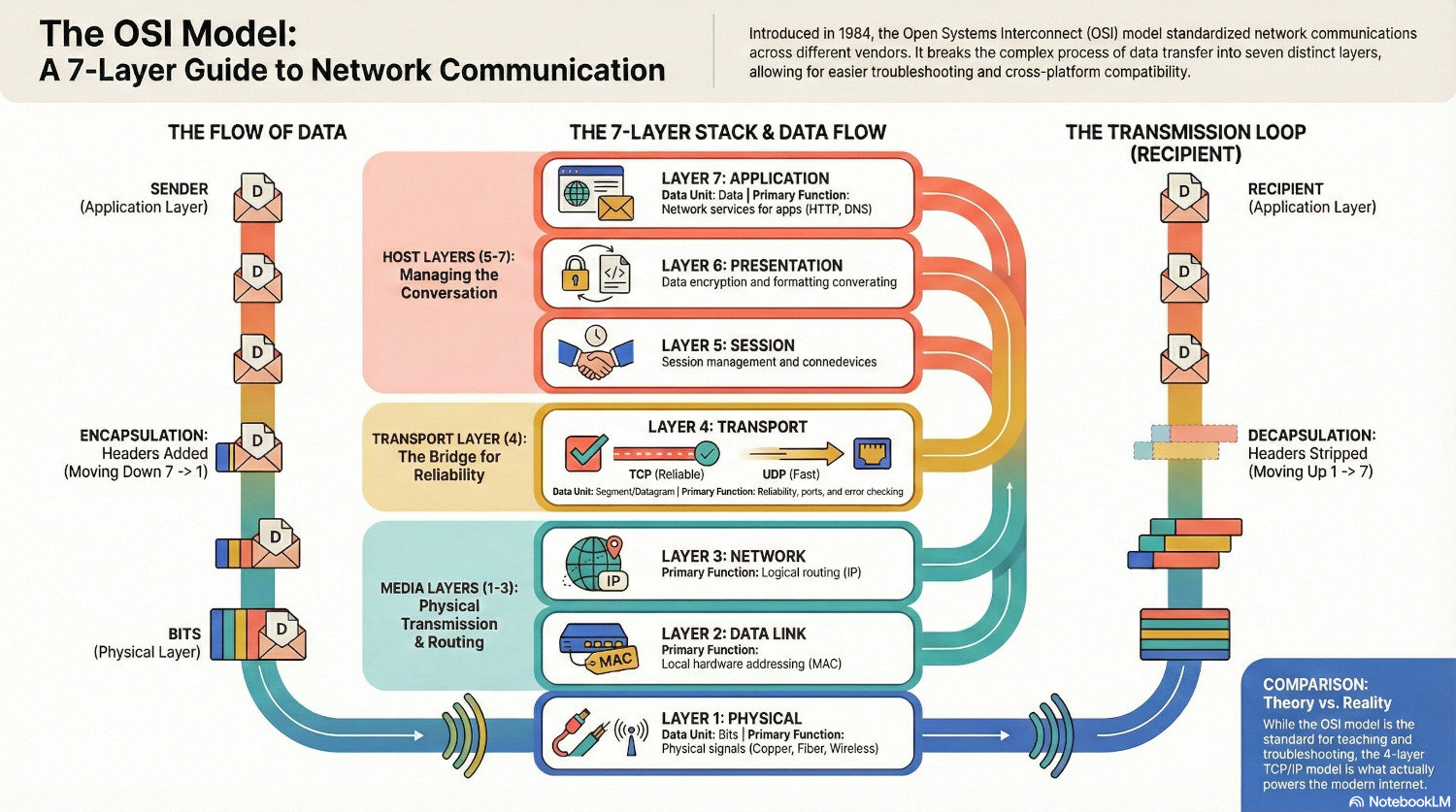
For data to get from one system to another, it has to start at Layer 7, work it’s way to Layer 1, then move back from Layer 1 to Layer 7 on the recipient.
At each stage, data is either added or stripped away, and being able to identify which layer you are working with is a major advantage when troubleshooting network communications.
However, while the OSI model is a theoretical map, it was preceeded by the TCP/IP model that actually runs the modern internet. The TCP/IP model contains only four layers, grouping similar functions like Transport and Session.
In the real world, we often use the OSI model to talk about networking, but we use the TCP/IP model to actually build it.