Spanning Tree Protocol (STP)
Redundancy is the key to a happy life. Never put all your eggs in one basket, relying on a single piece of equipment to keep users online.
This includes network cables and switches. If all the traffic has to get back to the core of the network, there should be multiple paths to get there. If there is only one, an ill-informed digger driver can take a network offline in one swift motion.
But unlike electricity, network traffic does not operate in a loop. In fact, loops are extremely dangerous for networks. So how we simultaneously need multiple paths to the same place, while knowing that having multiple paths to the same place is a huge problem?
That’s where Spanning Tree Protocol comes in. This protocol is designed to manage network links, ensuring that connectivity it maintained while prevented those dreaded loops.
Table of Contents
Network Loops
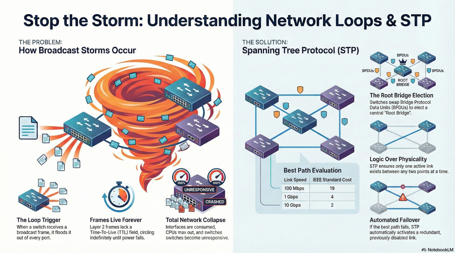
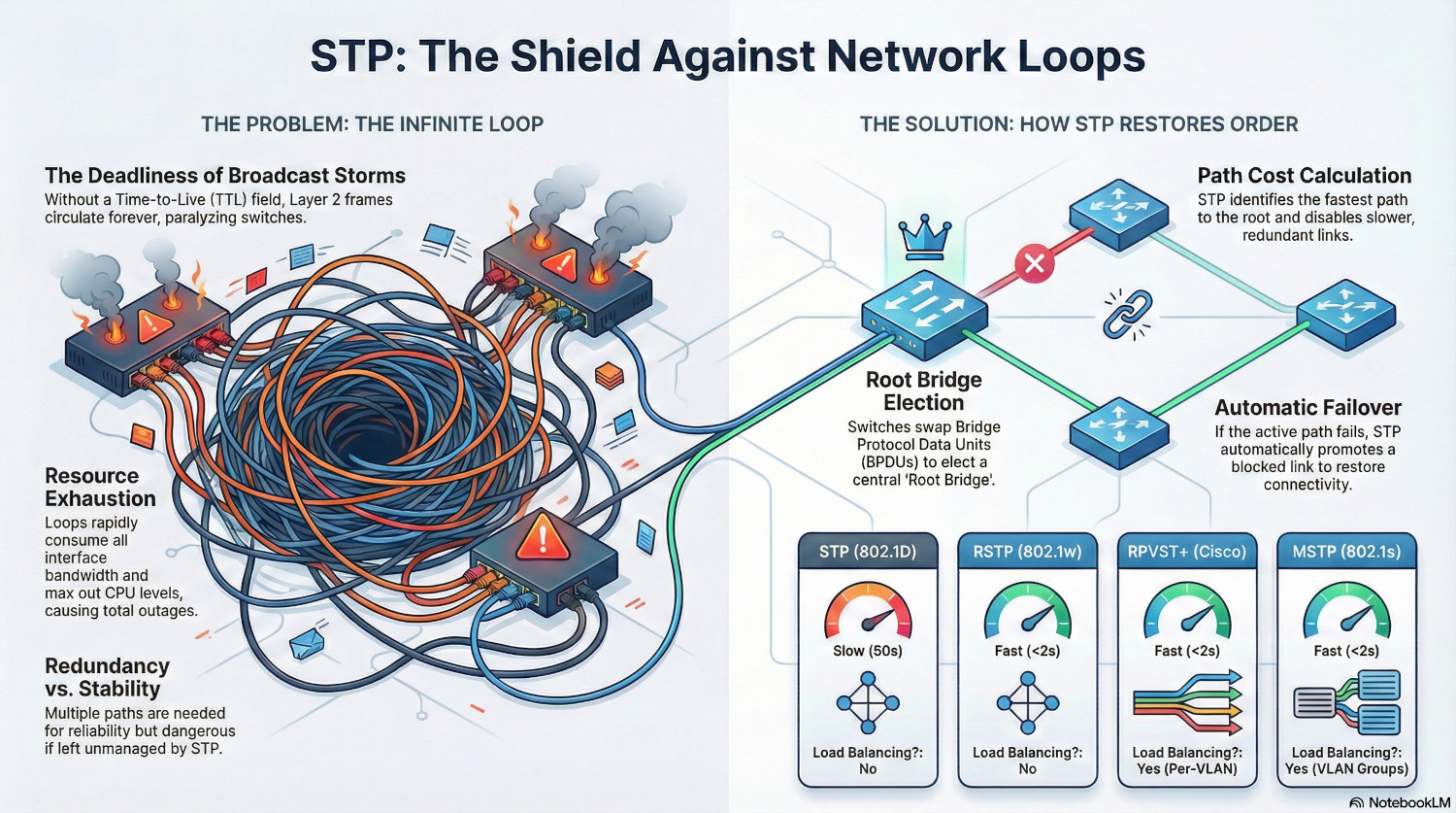
Network loops cause broadcast storms, due to the way layer 2 switching works. When a switch receives a broadcast frame (destination MAC FF:FF:FF:FF:FF:FF), or a unicast frame for an unknown MAC address, it sends it out of every port.
When there is a loop present, the frame is immediately received again by the same switch, which sees it as a new incoming frame, and treats it exactly the same way as the first; sending it out on every port again.
Unlike layer 3, layer 2 frames do not have a Time-To-Live (TTL) field, meaning they effectively live forever until they either reach their destination or power is killed.
Pretty quickly the interfaces are consumed by frames as they are sent over and over again. CPU can also max out and the switch can become unresponsive. Neighbouring switches are affected as well, as they are repeatedly sent the same broadcast frame.
A single network loop can quickly take down a whole network.
Spanning Tree Protocol (STP)
Spanning Tree Protocol was created in the mid-80s to find loop free paths around a network in a scalable way. Switches weren’t really a thing at this point - networks consisted mostly of hubs and bridges. However, STP was locked into the IEEE standard 802.1D, so the term bridges is still used today to refer to switches.
STP manages network topology, ensuring there is only one active link between any two points. If it detects multiple links, STP will decide the best link to use and shut down any others.
The tool STP uses to do this is called Bridge Protocol Data Units, or BPDUs. A BPDU is essentially a report, containing the Bridge ID and details about the links a switch has.
A BPDU will be addressed to the MAC address 01:80:c2:00:00:00 and contain the following:
| Bridge ID | The ID of the switch sending the BPDU. This is a 64 bit field, containing a priority (first 2 bytes) and the switch MAC address (last 6 bytes). |
|---|---|
| Root Bridge ID | This the is ID of the switch the sender believes has the lowest Bridge ID on the network. |
| Path Cost | This is the cost of the path the switch has back to the Root Bridge. |
The Root Bridge Election
The Root Bridge sits at the core of the spanning tree topology, and everything is based around finding the best way to get back there. This is usually the core switch of the network.
A bridge becomes the Root Bridge through a process called Election. Each switch swaps BPDUs and compares Bridge IDs and Root Bridge IDs. If a switch receives a BDPU with a lower Root Bridge ID than the one is currently has, it deletes it’s current Root Bridge ID and uses the received one.
Links and Paths
A link is a connection between two switches. A path is the route back to the Root Bridge.
Each link is given a cost. These can be defined manually, but are usually set by the STP protocol. The cost is predominantly determined by the speed of the link.
| Link Speed | Standard Cost (IEEE) |
|---|---|
| 10 Mbps | 100 |
| 100 Mbps | 19 |
| 1 Gbps | 4 |
| 10 Gbps | 2 |
A path cost is determined by adding the cost of all the links required to get back to the root bridge. If a switch has a 100Mpbs link to another switch that has a 1Gbps link to the root bridge, according to the IEEE standard the path cost would be 23.
If the switch has another path to the root bridge, it has a loop. If the second path has a cost of 38 (two 100Mbps links), STP will disable it as it has a higher cost than the first path. If the first path becomes unavailable, the second path is activated.
If two paths have the same cost, then a port priority can be used to act as a tie-breaker. The port priority is a multiple of 16, and the lower priority wins.
Port States
Legacy STP can place a port in one of 5 states. Modern versions, such as Rapid-STP simplify this to 3 states.
| State | Description |
|---|---|
| Blocking | A port in this state drops all traffic except BPDUs. |
| Listening | A port is sending a receiving BPDUs to determine if it is the best path. |
| Learning | This port drops traffic, but builds a MAC address table, preparing it for use. |
| Forwarding | A fully operation port. |
| Disabled | An administrator has shut down the port. It discards all traffic. |
STP Versions
STP (802.1d)
In classic STP, only the root bridge is actively sending BPDUs. All other switches receive the BPDU, update the costs and sender ID, then pass it on the their neighbours.
STP has a max age timer, that determines when a switch will determine a path dead. This timer is 20 seconds, so essentially it takes 20 seconds for a switch to notice if a path to the root bridge no longer exists.
Once STP is ready to jump into action, it places the port for any other paths in the listening state. This takes 15 seconds to check for any loops that may exist.
If the listening state reveals no loops, the port moves into the learning state, which takes another 15 seconds. It is still rejecting data, but it now starts learning MAC addresses and populating the MAC address table. This prevents it sending a flood of unknown unicast traffic when it becomes live.
Once this is done, the port moves to the forwarding state, and the link is now active. In total, this process takes 50 seconds, which is more than enough for users to notice.
RSTP (802.1w)
Rapid STP works differently, to enable switches to move between paths much quicker in the event of a failure. It replaces the timers used in STP with proposal/agreement handshakes instead. This results in failover times of under 2 seconds, instead of the 50 seconds in STP.
Instead of putting all other link ports in a blocking state if they are not active, RSTP designates alternate ports. These ports are like hot-standbys, they’re ready to go almost instantly if required.
RSTP doesn’t wait for BPDUs to stop before determining a link is down, instead relying on the link-state detection of the switch. As soon as the switch detects a link port going down, it triggers the RSTP protocol to switch to an alternate path.
Finally, RSTP uses an aggressive Topology Change mechanism that flushes MAC address tables instantly, ensuring traffic doesn't get lost in the transition.
PVST+
Per-VLAN Spanning Tree is a Cisco proprietary version of STP, that essentially creates a seperate spanning tree for each VLAN. The original PVST protocol used Cisco’s own trunking protocol until 802.1q VLAN tagging was adopted as the standard.
Because it uses the original STP timers PVST+ is just as slow to recover from failures, but the key feature it adds is load balancing.
Because the spanning tree topology is per-VLAN, each VLAN can have a separate root bridge. In other words, different traffic can be sent to different switches, utilising different paths. Instead of having redundant paths sitting unused, each link can be utilised for particular VLANs.
RPVST+
As the naming convention suggests, this replaces the STP logic with RSTP, making the protocol much faster but still implemented on a per-VLAN basis.
It is still a Cisco protocol, but there are similar implementation such as PVRST or Rapid-PVST. These protocols are interoperable with RPVST+.
The biggest issue with these protocols is the scalability, and the high CPU requirements if the VLAN count is very high. Each switch sends a BPDU for every VLAN every 2 seconds, resulting in a lot of processing for each switch.
MSTP
MSTP (802.1s) solves the CPU issue by grouping VLANs into logical instances. Each instance can contain multiple VLANs in an independant spanning tree.
This keeps the load balacning benefits of PVST but without the high CPU overhead, but is typically used in very large networks with hundreds of VLANs.
Version Summary
| Version | Standard | Speed | Load Balancing? | CPU Usage | Best Use Case |
|---|---|---|---|---|---|
| STP (802.1D) | IEEE | Slow | No | Very Low | Legacy hardware only. |
| PVST+ | Cisco | Slow | Yes | Low | Old Cisco networks with multiple VLANs. |
| RSTP (802.1w) | IEEE | Fast | No | Moderate | Small/Medium vendor-neutral networks. |
| RPVST+ | Cisco/Multi | Fast | Yes | High | Modern networks with <100 VLANs. |
| MSTP (802.1s) | IEEE | Fast | Yes | Moderate | Large Enterprises/ISPs with 100+ VLANs. |
Implementing STP
ℹ️ I’m using Cisco commands for this tutorial. Other vendors are available, and the concepts remain the same.
Phase 1 - Audit and Planning
The first stage in implement STP is to audit the network. Without a comprehensive and accurate network map, any STP implementation is doomed to failure.
These are the documents that you will need:
- Network Topology Map: List all the switches and links, including port details
- VLAN List: List all the VLANs in operation.
The next step is to decide which version to implement. Unless the network is full of old, legacy equipment, classic STP is out. If the network is multi-vendor, it needs to be an industry standard protocol. If it’s a Cisco network, the Cisco protocols are in play.
The best option for small to medium networks with a normal VLAN implementation is RPVST+, or one of the vendor implementations. This protocol has the benefits of load balancing and speed, without the additional complications of MSTP.
Phase 2 - Configure Root Switches
To implement load balancing, there needs to be two root bridges. One can be assigned to half the VLANs, the other to the other half.
On the first core, run the following commands:
Switch# configure terminal
Switch(config)# spanning-tree mode rapid-pvst
Switch(config)# spanning-tree vlan 1,2,3,4,5,6,7,8,9,10 priority 4096
Switch(config)# spanning-tree vlan 11,12,13,14,15,16,17,18,19,20 priority 8192
On the second core, run the following commands:
Switch# configure terminal
Switch(config)# spanning-tree mode rapid-pvst
Switch(config)# spanning-tree vlan 1,2,3,4,5,6,7,8,9,10 priority 8192
Switch(config)# spanning-tree vlan 11,12,13,14,15,16,17,18,19,20 priority 4096
Now the switches are set up with the correct priorities for the VLANs, and Rapid-PVST is enabled.
Phase 3 - Configure Core Link
The next stage is to configure the uplink between the core switches.
Switch# configure terminal
Switch(config)# interface gigabitEthernet0/1
Switch(config-if)# switchmode mode trunk
Phase 4 - Configure Distribution Ports
The ports on the core switches that connect to the edge or distribution switches need to be configured as trunk ports, and for the high availability link between both core switches, enable root guard. This stops any other switch taking over as the root bridge in the event of a misconfiguration.
Switch# configure terminal
Switch(config)# interface range gigabitEthernet0/2 - 12
Switch(config-if)# switchmode mode trunk
Switch(config-if)# spanning-tree guard root
Phase 5 - Configure Edge Switches
On each edge switch, run the following commands:
Switch# configure terminal
Switch(config)# spanning-tree mode rapid-pvst
Switch(config)# spanning-tree vlan 1-20 priority 32768
This enables RPVST+, and manually sets the priority for all VLANs. Technically, this is optional as it is the default, but I like to put it in there.
Phase 6 - Configure Uplink Ports
For the uplink port to the root switch, we want to set the priority, which should be a low priority to ensure it is the active port.
Switch# configure terminal
Switch(config)# interface GigabitEthernet0/24
Switch(config)# switchport mode trunk
Switch(config)# spanning-tree port-priority 16
For the uplink to the second core, set the priority to 32. This will make it the fallback in the event the first core path goes down.
For any links to neighbour switches, we want to make them a lower priority.
Switch# configure terminal
Switch(config)# interface GigabitEthernet0/23
Switch(config)# switchport mode trunk
Switch(config)# spanning-tree port-priority 64
Phase 7 - Configure Access Ports
For each access port, we want to put it in portfast mode and enable BPDUGuard. This means the port will skip the listening and learning phases and go straight to forwarding. But, if it receives a BPDU frame it will shutdown.
Switch# configure terminal
Switch(config)# interface gigabitEthernet0/1
Switch(config-if)# switchport mode access
Switch(config-if)# switchport access vlan 10
Switch(config-if)# spanning-tree portfast
Switch(config-if)# spanning-tree bpduguard enable
And that’s it!
Phase 8 - Monitoring
The most effective way of checking STP configuration is to run the following command on switches.
Switch# show spanning-tree summary
This will show the STP mode, the root bridge for each VLAN and the port states.
BPDU frames can be detected using Wireshark. Use the filter stp to see them.
If a more detailed view is required, run:
Switch# show spanning-tree detail
This will show granular details, including topology changes. If the topology change notification number is constantly increasing, that indicates a port somewhere is flapping between states.
To inspect an individual port, use:
Switch# show spanning-tree interface gigabitEthernet0/1
This will show you what state the port is in, overall and for individual VLANs.
SNMP traps can also be used; if a root ID changes or a port is moved between states, SNMP can be used to generate an alert.
Conclusion
With a solid implementation of Spanning Tree Protocol, a network moves from vulnerable to resilient, able to withstand equipment failure or damage and still keep users online.
By using modern STP implementations, redundant equipment isn’t sitting idle, but utilised to provide load balancing, safe in the knowledge that it will automatically take the full load if required.
Similarly to QoS, users will never notice STP. But they will notice broadcast storms, when every piece of network equipment is screaming and traffic grinds to a halt.