Quality of Service (QoS)
Picture a four lane motorway, but one lane has been cordoned off and marked ‘emergency services only’. The remaining three lanes can have a traffic jam, but ambulances and fire trucks will always get through.
That’s Quality of Service, or QoS. Traffic is prioritised and shaped according to classifications, ensuring high priority traffic can always get through and other traffic can be dealt with on a best effort basis.
A 100ms delay when opening a website is probably not going to upset too many people, but 100ms delay when on a phone call will cause problems, with audio breaking up and becoming unintelligible.
Table of Contents
How QoS Works

QoS works at both Layer 2 (Data) and Layer 3 (Network) of the OSI model to ensure that data can be prioritised whether it is encapsulated in a frame or a packet.
The key concepts of QoS are classes and policies. A class is a type of traffic, for example, TCP traffic using port 5060, and a policy dictates what priority is given to each class.
Class of Service (CoS)
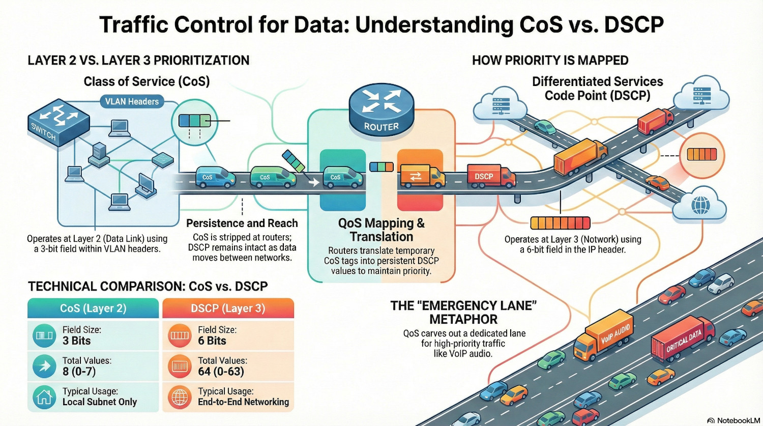
The layer 2 implementation of QoS is called Class of Service, or CoS. It utilises the Priority Code Point (PCP) field defined in the 802.1q (VLANs) standard. Because of that, layer 2 QoS is impossible on an unsegmented network.
The PCP field has a limit of 3 bits, so is restricted to 8 different values (2^3=8). Each value represents a priority level, with 7 being the highest priority traffic.
1 is actually classified as the lowest level traffic, as it allows administrators to relegate traffic below the default prioritisation of 0. The scavenger class is often used for backups, to ensure that heavy data transfers that can happen out of hours are not impeding user activity.
Because CoS lives inside the 802.1q header, it is stripped away as soon as the packet leaves the local subnet. For QoS to live on, it needs to be translated in DSCP.
| CoS Value | Priority | Acronym | Common Traffic Type |
|---|---|---|---|
| 7 | Highest | NC | Network Control (STP, LLDP, LACP) |
| 6 | Very High | IC | Internetwork Control (Routing protocols) |
| 5 | High | VO | Voice (VoIP RTP traffic) |
| 4 | High-Med | VI | Video (Streaming, Conferencing) |
| 3 | Medium | CA | Critical Applications (Database, ERP) |
| 2 | Low-Med | EE | Excellent Effort (Business Data) |
| 0 | Default | BE | Best Effort (Web, Email, Internet) |
| 1 | Lowest | BK | Background / Scavenger (Backups, P2P) |
Differentiated Services Code Point (DSCP)
DSCP is the layer 3 mechanism, that embeds the QoS marking in the IP header of the packet., specifically the Differentiated Services field. This makes DSCP persistent; it remains intact as the packet moves between routers and networks.
This field is 6 bits, so there are 64 possible values (2^6=64), and because there are many more possible values than available with CoS, DSCP can move beyond simple traffic prioritisation to complex shaping rules. However for compatibility reasons, not all 64 values are universally recognised.
These are the commonly used DSCP classes.
| Standard Name | Binary/Decimal Value | Common Usage |
|---|---|---|
| EF (Expedited Forwarding) | 46 | VoIP Audio (The highest priority) |
| AF41 (Assured Forwarding) | 34 | Video Conferencing |
| CS3 (Class Selector 3) | 24 | Call Signaling (SIP) |
| DF (Default) | 0 | Best Effort (Web, Email) |
| CS1 (Scavenger) | 8 | Bulk Data (Background updates) |
There are others classes that allow different types of video to be treated differently, but because CoS and WMM have fewer available classes, these aren’t always fully preserved across a network as a packet moves through different medium.
Wi-Fi Multimedia (WMM)
Quality of Service is arguably more important over wireless communications, given the half duplex nature of the communications. Instead of CoS or DSCP, a feature called Wi-Fi Multimedia, or WMM categorises traffic into four different priority groups.
| WMM Category | Description |
|---|---|
| AC_VO (Voice) | Highest priority, lowest latency. |
| AC_VI (Video) | High priority, guaranteed bandwidth. |
| AC_BE (Best Effort) | Standard traffic (Web, Email). |
| AC_BK (Background) | Low priority (Backups, Prints). |
Every wireless device must wait for silence before transmitting. WMM works by changing the amount of time a wireless frame must wait for. By shortening the wait time for high priority traffic, it ensures that Voice is transmitted before lower categories.
The wireless access point handles the translation between WMM, CoS and DSCP. When it sees a packet coming in tagged with AC_VO, it will add DSCP 46 and CoS 5 to the headers to ensure that QoS is maintained as it moves into the wireless network.
Another protocol is Mirrored Stream Classification Service (MSCS) that sits on top of WMM. It allows devices to instruct the AP to use the same classification for particular traffic, such as a phone call.
QoS Mapping
QoS mapping is the process of translating between the different QoS priorities, CoS, DSCP and WMM. As a packet moves between wireless, layer 2 and layer 3, the method of QoS changes and there needs to be mechanism to preserve QoS values.
Translations are defined in different RFCs.
| WMM Class | CoS Values | DSCP Values |
|---|---|---|
| AC_VI (Voice) | 5,6, 7 | 46 (EF) |
| AC_VO (Video) | 4 | 34 (AF41) |
| AC_BE (Best Effort) | 0, 3 | 0 (DF) |
| AC_BK (Background) | 1, 2 | 8 (CS1) |
QoS Security Considerations
Trust Boundaries
Because QoS allows traffic to be shaped according to rules, an attacker could potentially be able to take advantage of QoS logic to perform a denial of service attack, by flooding the network with high priority traffic leaving no space for standard user activity.
To mitigate against this, the trust boundary of QoS tags needs to be considered. Switches can be configured to ignore any CoS or DSCP tags associated with inbound traffic, and instead apply their own rules.
However, from an efficiency point of view, having Teams and VOIP phones identify and tag their own high priority traffic is a massive time saver for administrators.
The same logic works from the other end of wire. Traffic coming from the internet into the firewall can be tagged, but firewalls should be configured to strip any QoS away and apply it’s own logic.
Any policy can have exceptions, and if there is special consideration needed for a site-to-site VPN, this can be applied. But in general, everything coming from the internet should be treated with zero trust.
QoS Implementation Guide
Phase 1 - Audit and Plan
Before QoS can be implemented it needs to be carefully planned.
- Create a detailed list of all network infrastructure, including uplink capacities.
- Create a traffic analysis spreadsheet for each VLAN/subnet. Use packet captures and firewall logs to determine the different applications including ports and protocols in use and create a list.
- For each application, give it a CoS priority, a DSCP class and a WMM group.
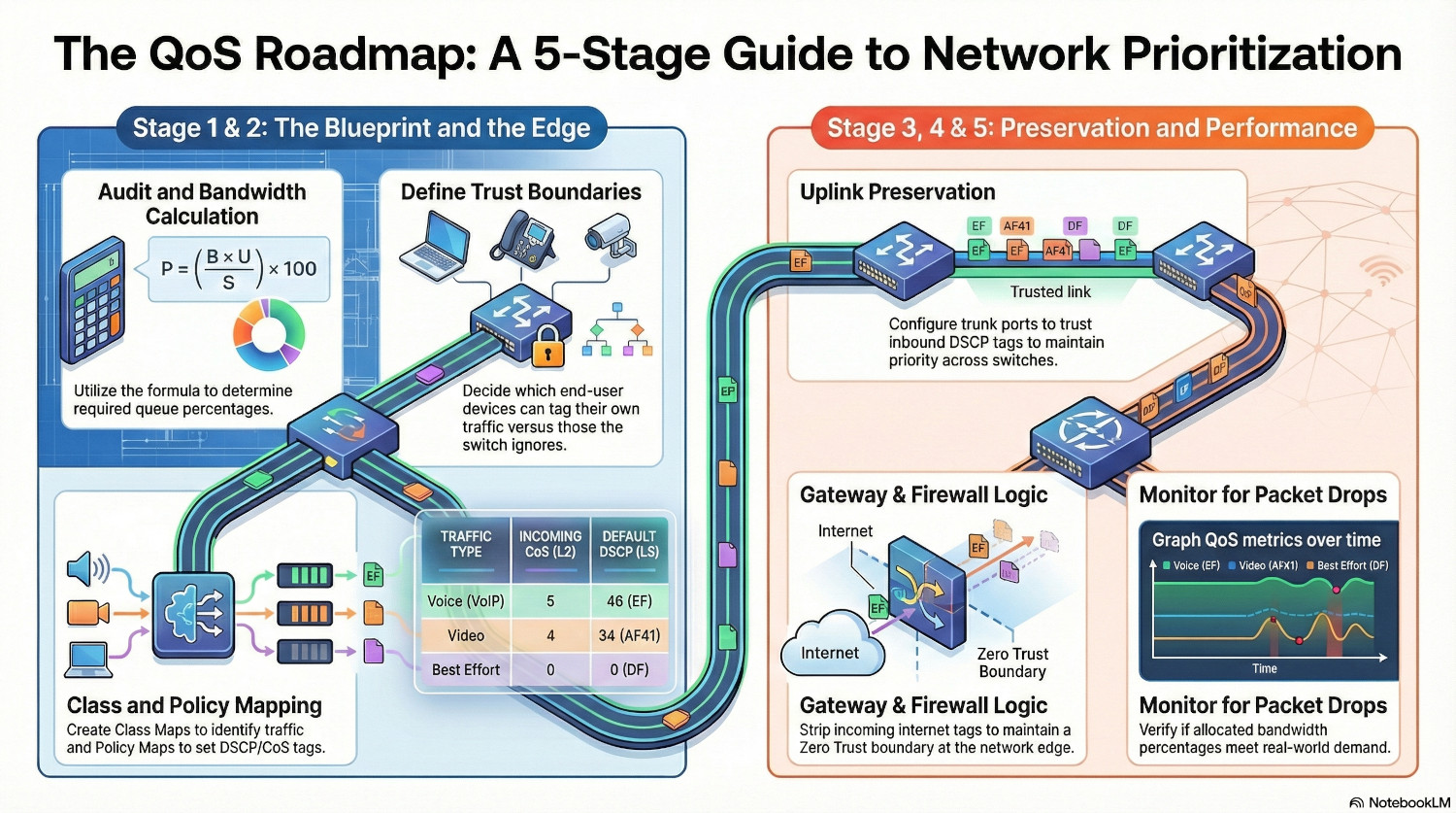
- For each application, we need to perform two calculations. One is the bandwidth consumption on an access port, and the other is the bandwidth consumption on an uplink port. This can be done using the following formula:
$$ P = \left( \frac{B \times U}{S \times 1000} \right) \times 100 $$
Where:
• P = Required Queue Percentage (%)
• B = Application Bitrate per user (in Kbps)
• U = Number of Concurrent Users/Streams
• S = Total Uplink/Interface Speed (in Mbps)
For the access port, we can assume that $U = 1$.
Let’s look at an example for an uplink port. Teams calling generally uses 2-3Mbps, and we’ll use the top end estimate for our calculations. If we expect 10 users to be on Teams calls, and we have a 1GB uplink, the calculation looks like this:
$$ 3 = \left( \frac{3000 \times 10}{1000 \times 1000} \right) \times 100 $$
10 users on Teams call simultaneously will use 3% of the 1Gbps uplink bandwidth. If we want to be cautious, we can add an overhead of 2% on to that and allocate 5% (50Mbps) of bandwidth for Teams calling.
Repeat this for any application that has been assigned anything other than default CoS or DSCP classes. You can manually assign allocations to any traffic you want to throttle.
Make a decision about trust boundaries. Decide which end user devices should be able to tag their own traffic and which shouldn’t.
Below is an example requirement list:
| Application | Protocol/Port | CoS | DSCP | WMM | Percentage |
|---|---|---|---|---|---|
| VOIP | TCP/5060 | 5 | EF46 | AC_VO | 5% |
| Teams | UDP/49152–65535 | 4 | AF41 | AC_VI | 5% |
Phase 2 - Access Ports Configuration
ℹ️ I’m using Cisco as an example here, other vendors will vary but the concepts remain the same. The ports given are also examples, there are lots of other ports required for VOIP and Teams!
Create the QoS class maps on the switches. This will differ according to vendor. To configure the VOIP requirements for Cisco we would do:
ip access-list extended ACL_VOIP
 permit tcp any any eq 5060

ip access-list extended ACL_TEAMS
 permit udp any any range 49152 65535

class-map match-any CLASS_VOIP
 match access-group name ACL_VOIP

class-map match-any CLASS_TEAMS
 match access-group name ACL_TEAMS
This tells the switch to permit any traffic on TCP port 5060, and then map the ACL with a class that we can then configure then policy map:
policy-map QoS_Edge
 class CLASS_VOIP
  set dscp ef
  set cos 5
  priority percent 5

 class CLASS_TEAMS
  set dscp af41
  set cos 4
  bandwidth percent 5
Now the switch knows to tag traffic identified by the VOIP ACL as CoS priority 5, DSCP Expediated Forwarding.
The priority percent 5 line ensures that any traffic using that class is sent immediatetly, jumping in line before anything else. The 5% is both a guarantee and a limit; if the interface is full any traffic over the allocated 5% will be dropped.
The bandwidth percent 5 line ensures that traffic is favoured, but other traffic is still allowed to be processed. The 5% is guarantee; if the interface is congested, 5% is reserved for this traffic, but it can use more if required.
While it may seem counter intuitive that the excess VOIP traffic gets dropped, this is actually to protect the switch and network. Because the traffic is sent immediately, it can quickly prevent any other traffic being sent.
Finally, the policy needs to be assigned to a port.
interface GigabitEthernet1/0/1
 service-policy input QoS_EDGE
Alternatively, you can configure the port to trust incoming DSCP tags, but use the policy to apply the bandwidth limits and catch untagged traffic.
interface GigabitEthernet1/0/1
 mls qos trust dscp
 service-policy input QoS_EDGE
Phase 3 - Uplink Port Configuration
Now the traffic is tagged with QoS, the neighbouring switches need to trust the traffic being sent to them to ensure QoS is preserved as it moves through a network.
This needs another class map:
class-map match-all CLASS_VOIP_TRUSTED
 match dscp ef
class-map match-all CLASS_TEAMS_TRUSTED
 match dscp af41
This assigns a class to any traffic tagged with EF or AF41.
We also need another policy map:
policy-map QoS_Uplink
 class CLASS_VOIP_TRUSTED
	priority percent 5
 class CLASS_TEAMS_TRUSTED
  bandwidth percent 5
This sets the bandwidth and priority for the classes.
Then the policy can be assigned to the uplink port.
interface TenGigabitEthernet1/0/1
 mls qos trust dscp
 service-policy output QoS_Uplink
Note that we’re doing two things here - we’re trusting inbound DSCP tags from the neighbouring switch, and we’re applying the QoS_Uplink policy to outbound traffic.
Now QoS is being honoured right across the network.
Phase 4 - Gateway Configuration
The final stage is the most important - all this work was for nothing if the QoS tagging is dropped by the gateway.
The gateway device need to be configured much the same as the switches; trust the tags coming from inside the network, and apply it’s own tags to traffic coming from the internet.
The firewall should also honour DSCP tags for traffic leaving the network, but there needs to be realistic expectations that QoS may not be honoured for the rest of its journey, but at least you’re giving it a fighting chance.
ℹ️Many enterprise internet connections will offer a QoS SLA, in which case DSCP tags will be honoured.
Phase 5 - Monitoring
Monitoring QoS is an important part of the implementation process. Uplink capacity monitoring is an important metric of network health; an overloaded uplink is going to be a bottleneck for everything.
With QoS, it’s important to verify that the calculation performed in stage 1 have translated into the real world. Maybe more users than expected are using Teams simultaneously, and the 5% bandwidth reservation is not enough in busy periods.
There are different methods for each vendor on how to pull the data, but really it should be integrated into your monitoring system and graphed over time. The key metric to look for is packet drops; is traffic getting dropped because the 5% limit is being exceeded?
QoS can be checked using Wireshark to check the packets are tagged appropriately using the following filters.
| QoS Tag | Filter |
|---|---|
| CoS | vlan.priority == $cosvalue |
| DSCP | ip.dsfield.dscp == $dscpvalue |
Conclusion
By moving away from a best-effort based network where all traffic treated equally, to an intent-based configuration where traffic is treated according to business needs, administrators take control over their estate.
Troubleshooting glitchy phone calls is a frustrating experience for everyone, and no-one likes the dreaded ‘bad network quality’ pop up in a Teams call.
An important point to note is that QoS is not a fix for a network that is consistently saturated. If there is a 1500Mbps trying to get down a 1000Gbps pipe, there are going to be problems no matter how much QoS is applied.
QoS is for ensuring that when a link is momentarily full, a large download, critical traffic is still able to get through.
Try and explain QoS to and end user and they will probably glaze over, but for sysadmins it’s another tools working quietly in the background to make lives easier, and ticket queues shorter.